This Tutorial shows how to setup the markers on the floor and how to configure the ground plane triangle to get the best calibration results with spatial augmented reality.
In order to get a perfect alignment of the tracking system with the calibration model for spatial augmented reality, the floor of the IA[space] needs to be marker-ed in a specific way.
the main marker its the one in the center of the space, where the ground plane is placed in such a way, that it points with the longer end towards the gate, and the shorter end, with the laser pointer attached, towards the side where the audio table is located.
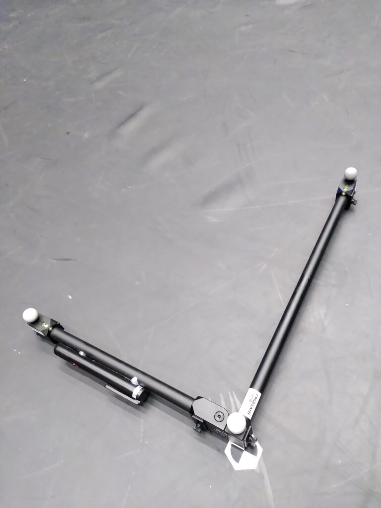
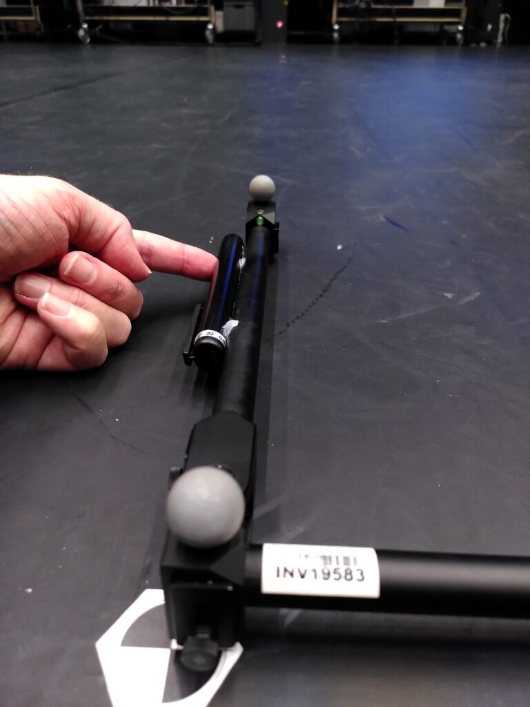
It is important not to make any other adjustments at the frame, like turning the leveling wheels on both ends. they have hot-glue points to prevent any changes, since this would break the setup.
This tutorial is here to show how to setup all the markers, the ground plane etc. to get the highest quality results possible.
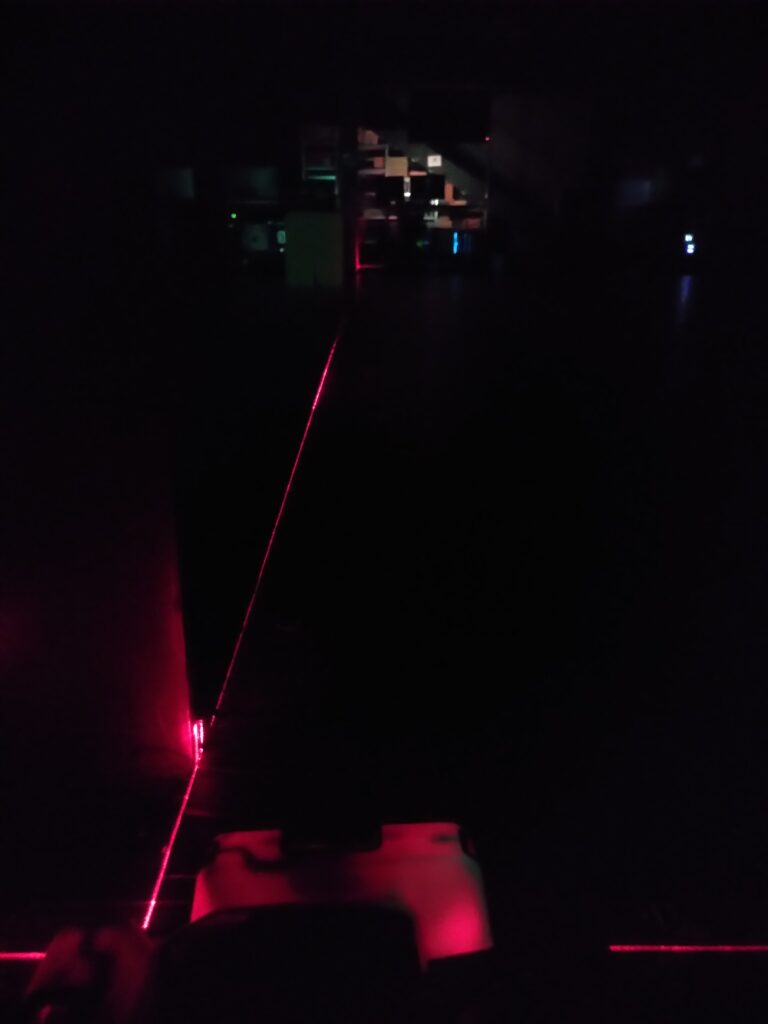
First you need a line laser to align between the two center columns as shown. the laser has to touch the right edge of both columns on both sides of the space. the center target-marker will be placed on this line.
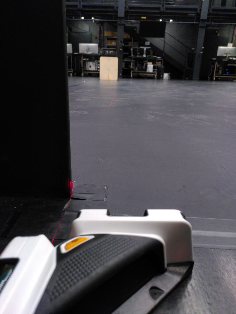
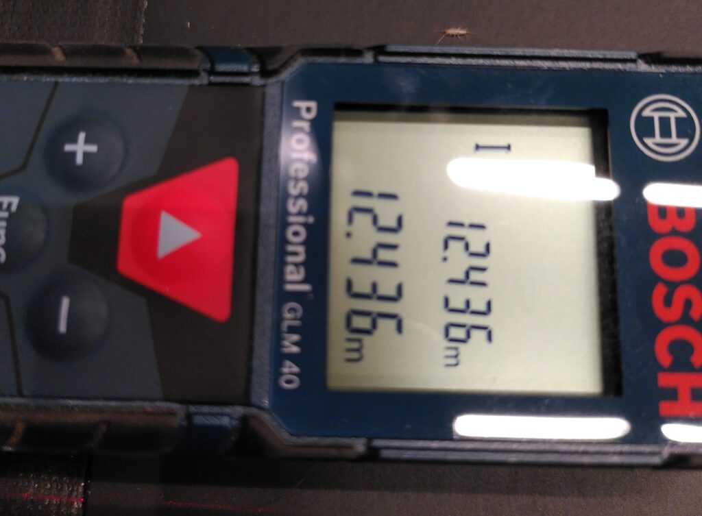
Then you can measure the exact distance between the two columns.
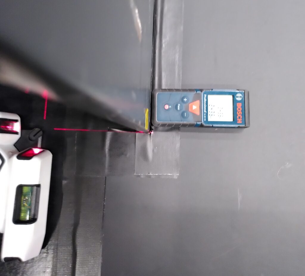
Its should be around 12.436 – 12.438 meters. the target-marker should be placed exactly into the center, so at 6.218 or 6.219 meters.
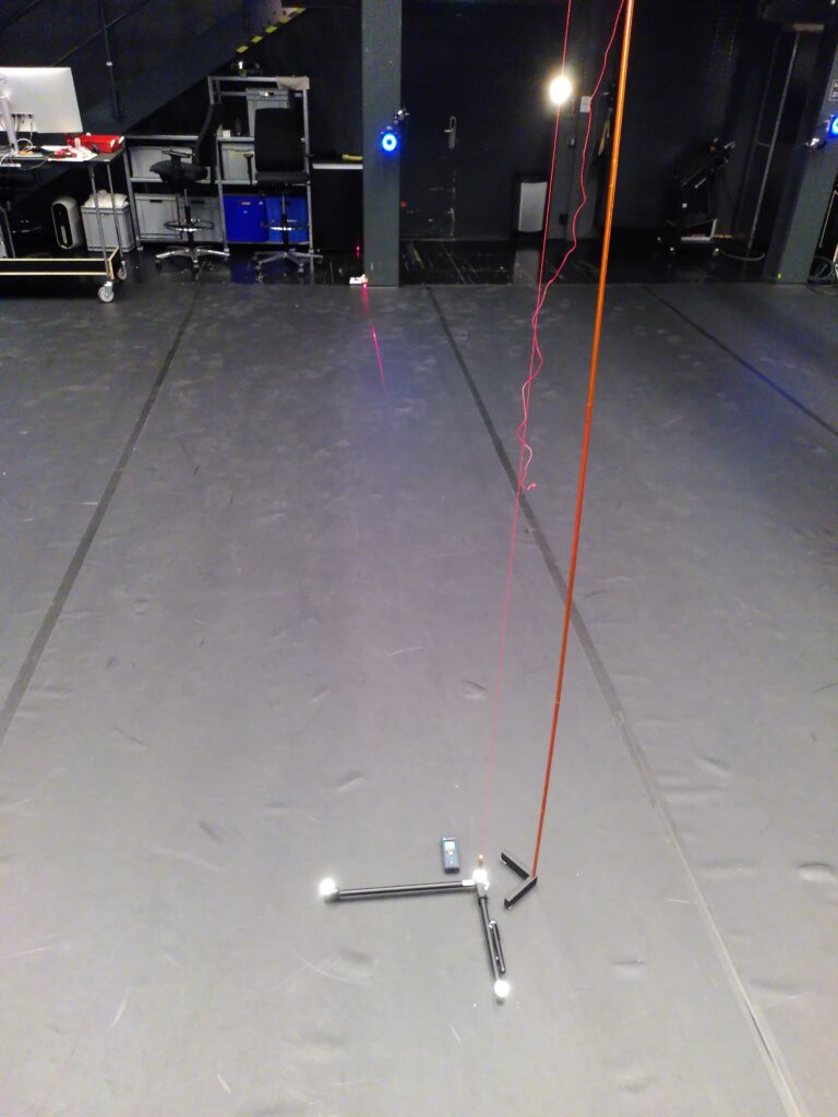
Once the main center target-marker is set, you can place the ground-plane frame as it should be placed approximately.
In this next step we will adjust the leveling wheels. to that we need to setup a plumb-line with an additional reflector right on top of the corner reflector on the ground-plane frame.
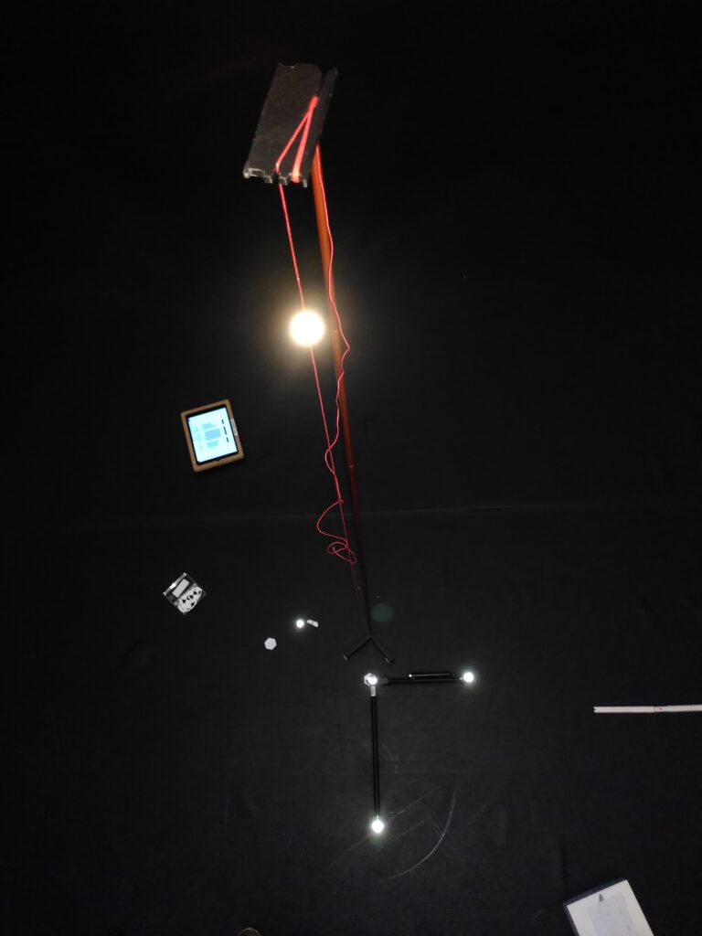
once the additional reflector is perfectly placed, the next step is an iterative adjustments of the leveling wheels:
- adjust the leveling – wheel on one axis
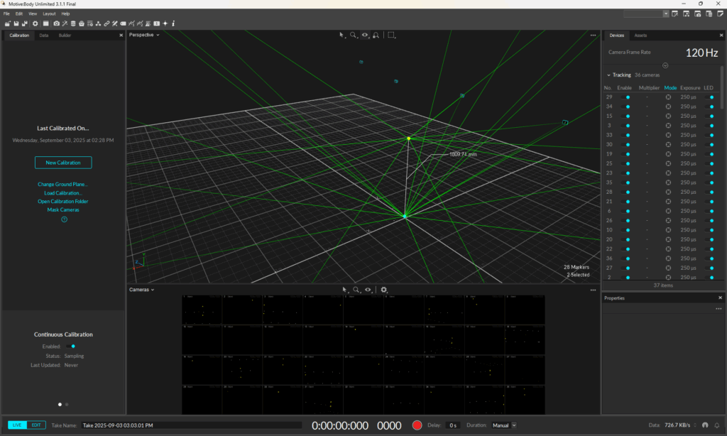
- inside motive, set the ground plane
- look at the 3d view (orthogonal – top)
- adjust the wheel until the two reflectors overlap
- repeat step 1
- once that axis is ok, do the same with the other axis then until the two reflectors are perfectly above each other
In the last step, set a reflective marker on the x-axis at the 3 meter spot.
make sure the marker is on the laser-line.
rotate the ground-plane frame – then inside motive set ground plane – and repeat this until the reflective marker shows up inside motive spot on the grid at the x=3 meter, y=0 meter mark.
now the ground-plane frame is properly alligned.
press the laser-pointer and set a target-marker on the spot the pointer shows.