Co-Experiencing Virtual Spaces is a framework in the game engine Unity which allows co-location tracking of multiple VR glasses in the same real space as well as in the same virtual space. By an initial calibration of the devices with the help of the controllers in the center of the room, an absolute zero point in the room can be generated for all of them, at which the virtual environment aligns itself. A paper about the development of this framework was also published in which more details are described: Link Paper
Requirements
Tested with Unity Version 2021.3.1f1 and need the Android Build Support module. There are some .blend files in this project. For these to work properly blender 2.8 or higher must be installed on the device. The framework uses the Oculus integration for Unity and can be built for the mobile standalone VR glasses Oculus Quest, Quest 2 or Quest Pro.
Editor
Settings
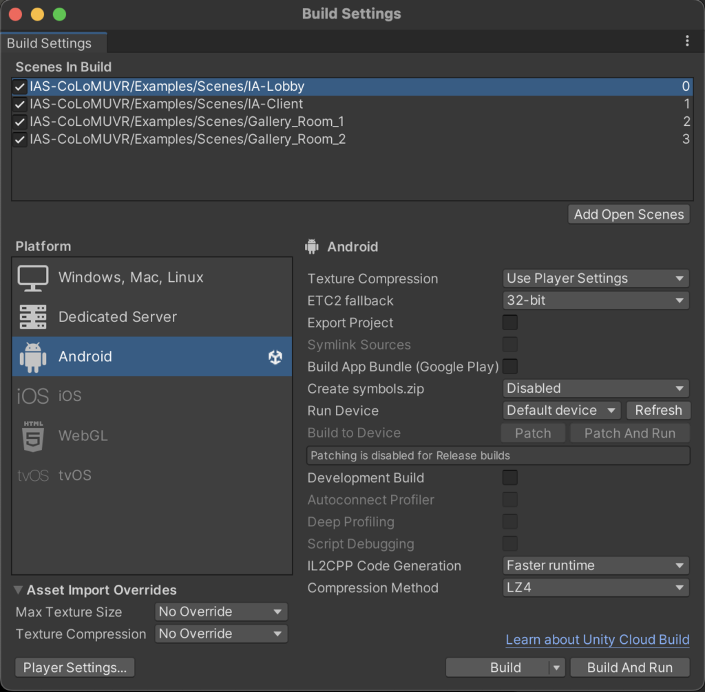
Most importantly you need to switch to “Android” in the build settings.
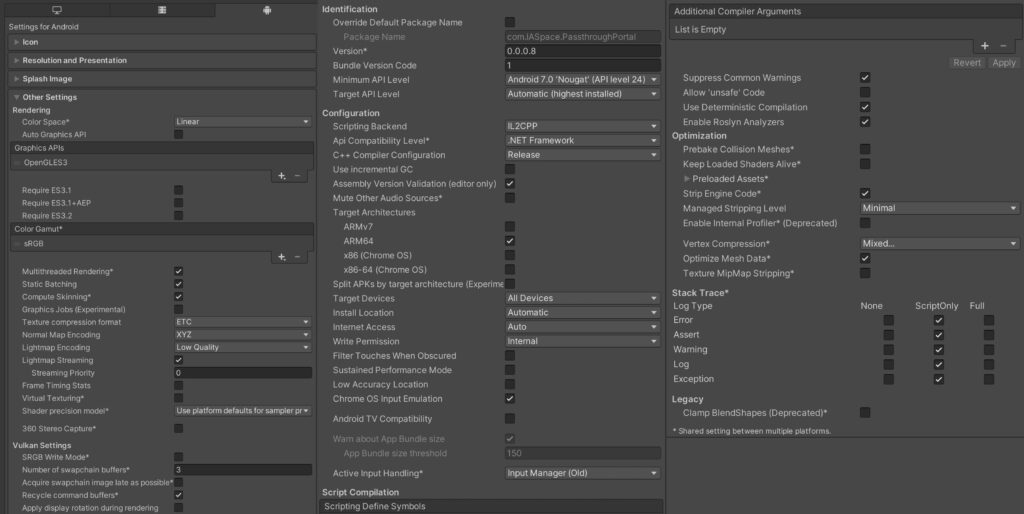
You need the following Player Settings so everything of the project works.
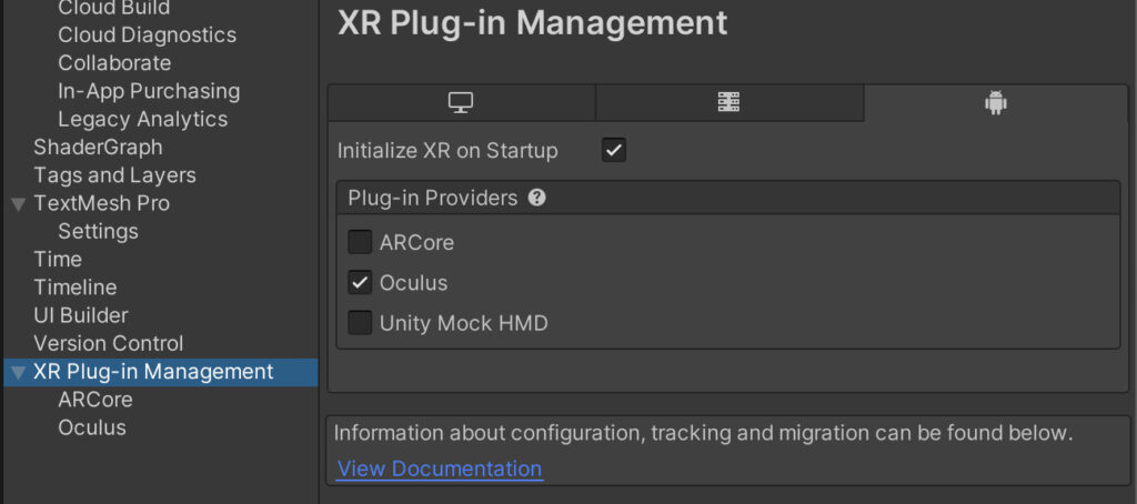
Activate XR in the “XR Plug-in Management” and add the Oculus Plug-in for android.
Project Structure
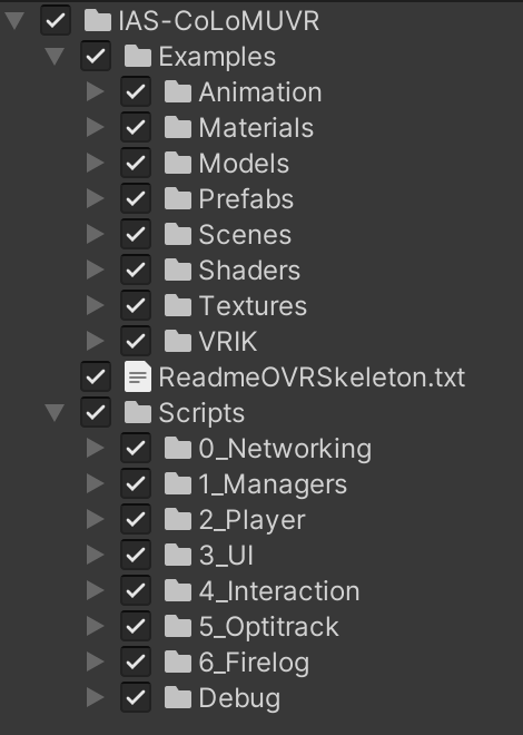
All components of this system can be found in the IAS-CoLoMUVR folder. This is divided into Examples, which contains scene, prefabs and other example assets, and the Scripts folder. The examples serve as sample objects and scenes, which can be changed or completely replaced with your own.
Scenes
The lobby scene “IAS lobby” serves as the local menu and the first scene that gets started for the application. In these, a game can be started and existing games can be joined. The “IAS-Server” serves as an example for a passive scene which is not a host and therefore not a client. This should not be run from the Oculus Quest. The client scenes serve as game scenes which are automatically started by the network and can be changed in the “MenuUI” object of the respective lobby on the MenuUIManager components. The “NetworkManager” object remains over all scenes (DontDestroyOnLoad).
Prefabs
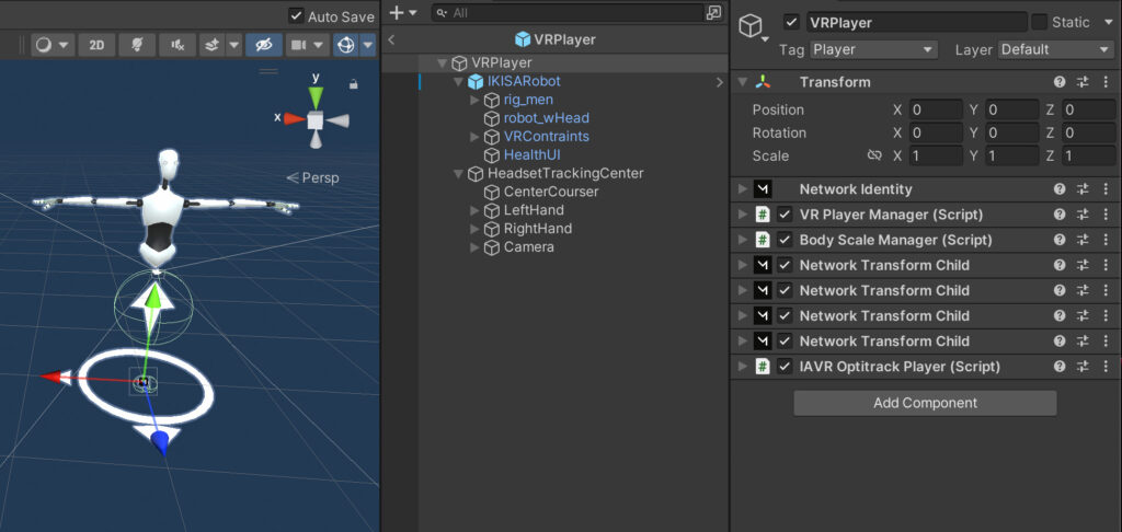
VR Player
This contains the VRRig for the player and the visual body. In a non-local instance of this prefab (player), unneeded components such as the “Camera” or “VRController” are deleted at startup.
- Controller gestures and complete finger tracking over the network
- Simple Ik body which follows hands and head tracking
- BodyScaleManager with which the size can be calibrated via a T-pose in the lobby
The VR controllers can be used to grab objects with the “GrabableNetworkingObject.cs” which adjust their network authority.
Menu UI
In the menu UI you can add new selectable game scenes for the players or are completely new functions. To be intractable by the right hand ray caster, an object needs a collider, a “InteractiveEvent.cs” component and must be on the UI layer.
PauseCalibrationUI
This interface allows the user to start the calibration process. This is opened via the menu button on the left touch controller. A view direction bound courser can be interacted with as the controllers are used for the calibration.
Grabbable Cube
This is an example prefab of an object that can be grabbed by players that is also synced over the network. For that you mainly need the “GrabbableNetworkingObject.cs” component.
The most important values to change are the “snap to center” when getting grabbed or the grab type. Which can be “Velocity”, with that the object follows the hand with a delay based on the mass of the object and also can collide with other objects. “Instantly”, with that the object follows without a delay but can’t collide with other objects, or “None”.
Changes made to the Oculus Integration:
In order to enable a full body IK Mesh with the Oculus Quest finger tracking, some changes had to be made to the OVRSkeleton.cs of the Oculus Integration. If you reimport or update the Oculus Integration, you have to change them again.
1.First, add the following code at line 115 in the OVRSkeleton.cs
public enum BoneOrientations { FromQuatf, FromFlippedXQuatf , FromFlippedZQuatf };

public BoneOrientations fingerBoneOrientations = BoneOrientations.FromQuatf;
2. Change the Update function at line 330 to LateUpdate function
3. Change at line 404 the Update(); to LateUpdate();
4. Delete the following Code at line 378:
_bones[i].Transform.localRotation = data.BoneRotations[i].FromFlippedXQuatf();5. Add the following Code at line 378:
if (this.fingerBoneOrientations == BoneOrientations.FromFlippedXQuatf)
  _bones[i].Transform.localRotation = data.BoneRotations[i].FromFlippedXQuatf();

else if (this.fingerBoneOrientations == BoneOrientations.FromFlippedZQuatf)
  _bones[i].Transform.localRotation = data.BoneRotations[i].FromFlippedZQuatf();

else
  _bones[i].Transform.localRotation = data.BoneRotations[i].FromQuatf();
6. Add the following code at line 450:
public float GetRootScale(){
  if (!IsInitialized || _dataProvider == null)
      return 1f;
  else
      return _dataProvider.GetSkeletonPoseData().RootScale;
}
7. Open the LocalVRPlayer prefab, in the child Object HeadsetTrackingCenter, select the LeftHand and change on the OVRCostumeSkeleton Component the FingerBoneOrientation to FromFlippedXQuatf
Networking (Mirror)
For the networking between the multiple devices, the open-source system Mirror is used. Mirror works on the Client Server Model.
Code changes
If you re import or update the Mirror Package, in the NetworkManager.cs, in the line 732 you have to make a change the code from:
void RegisterClientMessages();to:
public virtual void RegisterClientMessages();Network Manager
The Network Manager handles all the connections of the network. It can start a server or host or find running servers via the “NetworkDiscovery” component. On the NEtwork Manager you can change values like the max Player count and the Server Tick Rate.
If you want to use another player prefab, add it in the “NetworkManager” VR Players Prefabs. For Mirror to instantiate a prefab over the network on other devices too, you also have to add these prefabs under “Registered Respawnable Prefabs”.
Networking Objects
Objects that have components to exchange data on multiple devices like the “VR Player” or the “Grabbable Cube” always need a “NetworkIdentity” component and can’t be a child of another object in the hierarchy.
Mirror already has multiple prepared components to exchange the transform or rigidbody data over the network. If you want to create an own Component to exchange data between the devices, follow this Network Behaviour tutorial.
Optitrack Integration
The system can be extended with an Optitrack tracking system to track more objects or whole persons. Here is a tutorial on how the system basically works with Unity. For it to work with the co-location system and networking, slightly modified components must be used.
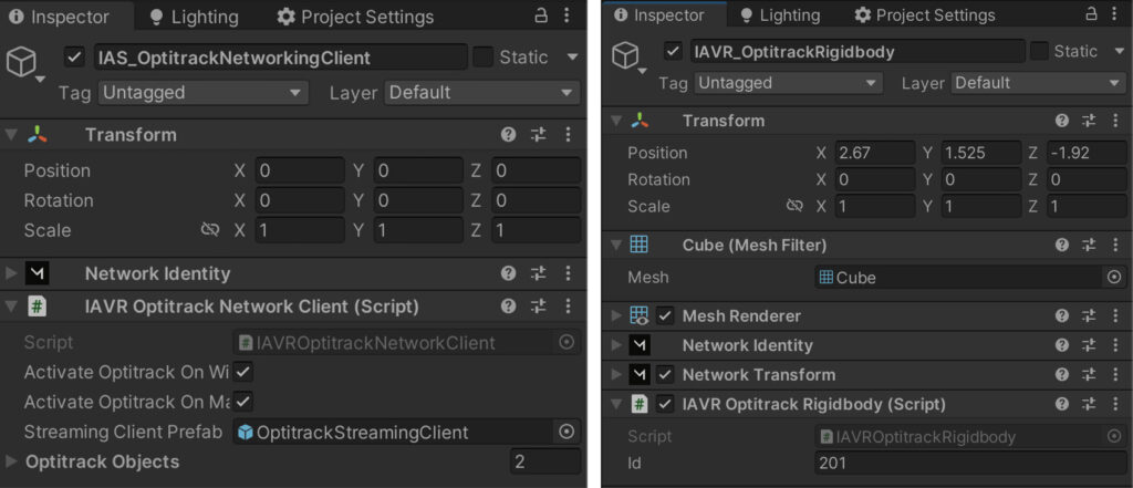
Any game instance (server, host or client) running on a Windows computer can receive the Optitrack data directly from Motive via the local network. If a client runs on VR glasses (Android based), a server must run on a Windows computer that receives the Optitrack data over the local network and then sends it to the Android client.
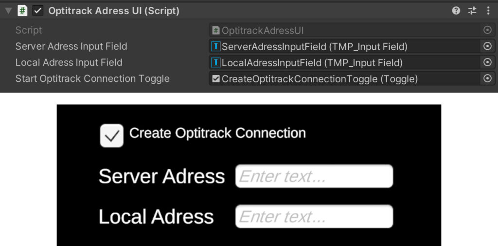
If the “IA-Client” or “IA-Server” scene is started on a Windows machine, you can see in the top left corner a optitrack connection UI. Activate the toggle if you want to connect with the Motive on this instance, then type in the ip address of the Motive PC in the server field and the ip address of itself in the local field.
IAVR OptitrackRigidbody
For an object to get updated by an Optitrack rigidbody, you have to add in addition to a “Network Transform” component the “IAVR Optitrack Rigidbody” with the correct Id that you can change in Motive. This component then will automatically either receive the orientation directly from motive or over the server instance if there is no Optitrack connection on this instance.
Headset center calibration by Optitrack
If the Optitrack system is used to track further objects, it can also be used to automatically align the position of the individual glasses with each other without having to perform the calibration with the controllers. This can be selected per headset. If a pair of glasses wants to adjust automatically, an Optitrack marker must be attached, this must be set up as Rigidbody in Motive and provided with an ID from 41 to 46 (the system could also be supplemented with further numbers).
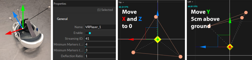
It is also possible to set up glasses without markers using the controller calibration described below. Please note that the zero-point calibration is done at the same point as the Optitrack systems zero point is.
IAVR OptitrackSkeleton
Motive skeleton objects work much more complex, because they have to transmit not only one position and rotation but many of all bones. To optimize the data that has to be sent over the network, the unity IK system is used to only transfer the position of some key points. For the system to know what skeleton data it should apply, you have to change the skeleton name to the name used in Motive.
Passthrough Mixed Reality
The passthrough system allows us to show the real camera image of the VR-headset behind or over the virtual world or on specific objects.
Passthrough Layer
The “PassthrougLayer” component activates the Passthrough and gives you options to customize it. You can find it on the “Game Manager” Object where also the “OVRManager” is situated. Under the following link you can find more informations about passthrough and how to apply the passthrough only to specific objects:
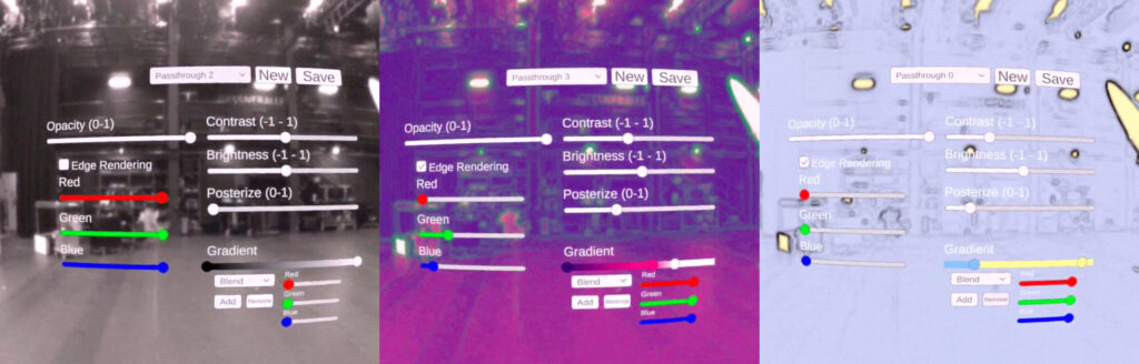
Passthrough Editor
A problem of the passthrough customization is that you don’t see the changes you made in the editor. So a passthrough editor to use in the VR headset was created: Github Project
Map virtual and real Room
This section is about how to align the virtual copy of a real space in VR so that they match.
When creating the 3D model in e.g. Blender or with a scanner (e.g. iPad) you have to pay attention especially to where the zero point is and how the orientation of the world is.
The zero point should be located in the center of the room to reduce inaccuracies at a greater distance from the room. Furthermore, the calibration is easier to perform if the zero point is located at prominent corners in the room where all players with the VR goggles can perform their calibration as accurately as possible. This could be between a door frame, for example, or at the corners of a table.
Bild: 3D Modell with Origin and orientation + Real spot calibration
Runtime
Oculus Link
You can use Oculus Link or Air Link to connect a VR-Headset with a Windows PC and test the application in the Unity editor without the need of a build.
Build
When you build the application, be sure that you switched to the android build support and that your lobby scene is the first in the build settings.
Install
There are multiple ways to install the built .APK on your quest device. If you are using an own Meta Account and not the VR-Headsets setted with the IAS account, you have to activate the developer functions for your account and device. https://aixr.org/insights/how-to-enable-developer-mode-on-oculus-quest-2/
ADB: https://developer.oculus.com/documentation/native/android/ts-adb/
Meta Quest Developer Hub: https://developer.oculus.com/documentation/unity/ts-odh/
Start Application
After you installed the application on the VR-Device, you can find it in the library, when you change the dropdown on the top right to “Unknown Sources”.
Calibration
Each pair of VR glasses uses its own zero point in space and initial orientation at the outset. In order to define the absolute zero point in the room for the headsets to be co-located, all users must take turns performing a calibration with their controllers. Thus, if all users place their right controller on a marked point in space, which is ideally arround the center of the room, and the left controller on a second marked point representing the forward orientation of the virtual environment, each user can generate an equal zero point in the real world. It’s important that all users place and align the controllers on the same points.
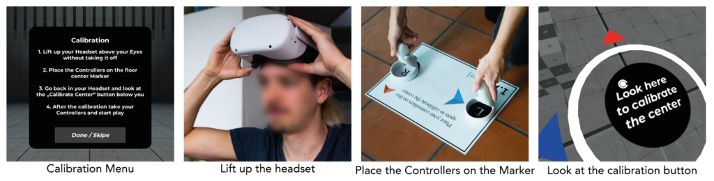
If you use the passthrough functions to see the real world with the built in cameras of the headset, you don’t have to lift up the headset any more.
Tracking improvements
Poor lighting conditions or monotonous rooms can lead to position shifts or the suspension of the inside-out tracking of the VR glasses. Under these conditions, glasses can sometimes recover their positioning and only suffer from small displacements but most shifts are larger and the user has to recalibrate the zero point. On the other hand, if the rooms are well illuminated, tracking usually works very well, even over several floors. To improve the tracking in low contrast rooms, we put lines and symbols with white tape all over the floor area, including on some walls to increase the details in the room.