Please follow these steps for each motion capture session:
- Setup Tracking Suit or 6 Rigid Body Skeleton
- Setup Rigid Bodies
Setup
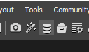
Before you start capturing you need to setup your session. First you have to open the Data Pane:
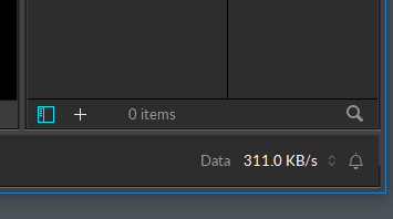
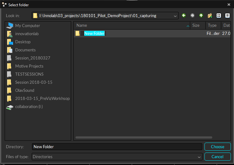
Press the plus-icon to select a new session folder. You need to create a new session inside your projetct on the internal drive D:
D:\01_Projects\YOUR-PROJECTNAME\Motive
If necessary create a new subfolders with a distinctive name with a date eg. Session_180329.
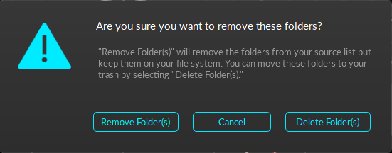
Then you need to remove all the other sessions from previous uses:
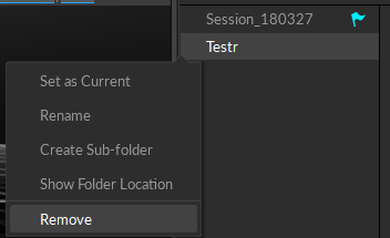
ATTENTION: PLEASE make sure you only REMOVE the folders. DO NOT DELETE THEM!!!
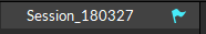
Set the blue flag to make sure your new session folder is active and all new takes will be stored inside this folder.
For more detailed information you can check the official documentation.
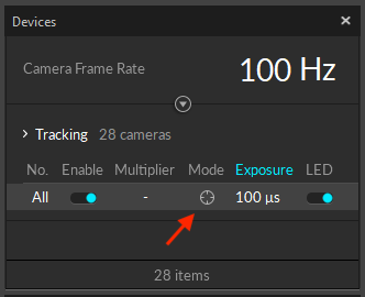
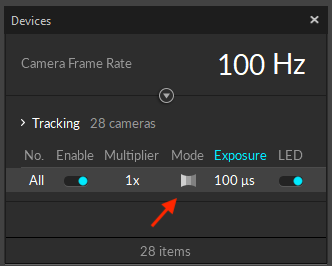
Check in the Devices pane that all cameras are set to Enabled and LED are On.
Switch cameras to video mode by selecting all cameras in the Device pane and then pressing the crosshair symbol to identify reflections in an area.
Make sure no reflective objects are visible to the system. Remove all all reflective objects from the space or cover them. Many shoes have actually reflective surfaces, so make sure to either tape them or take them off for the following processes.
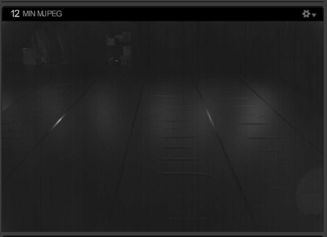
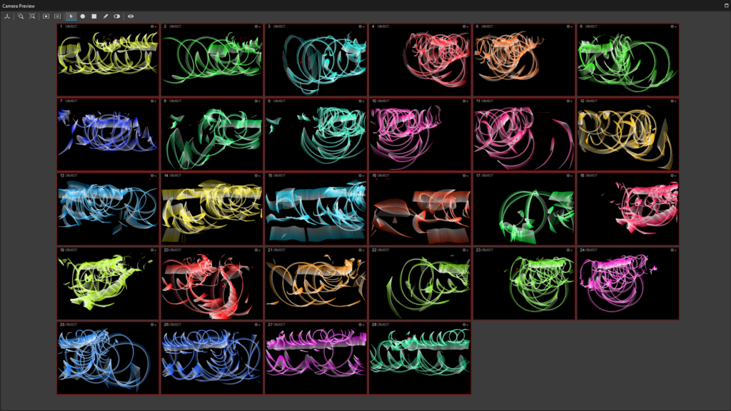
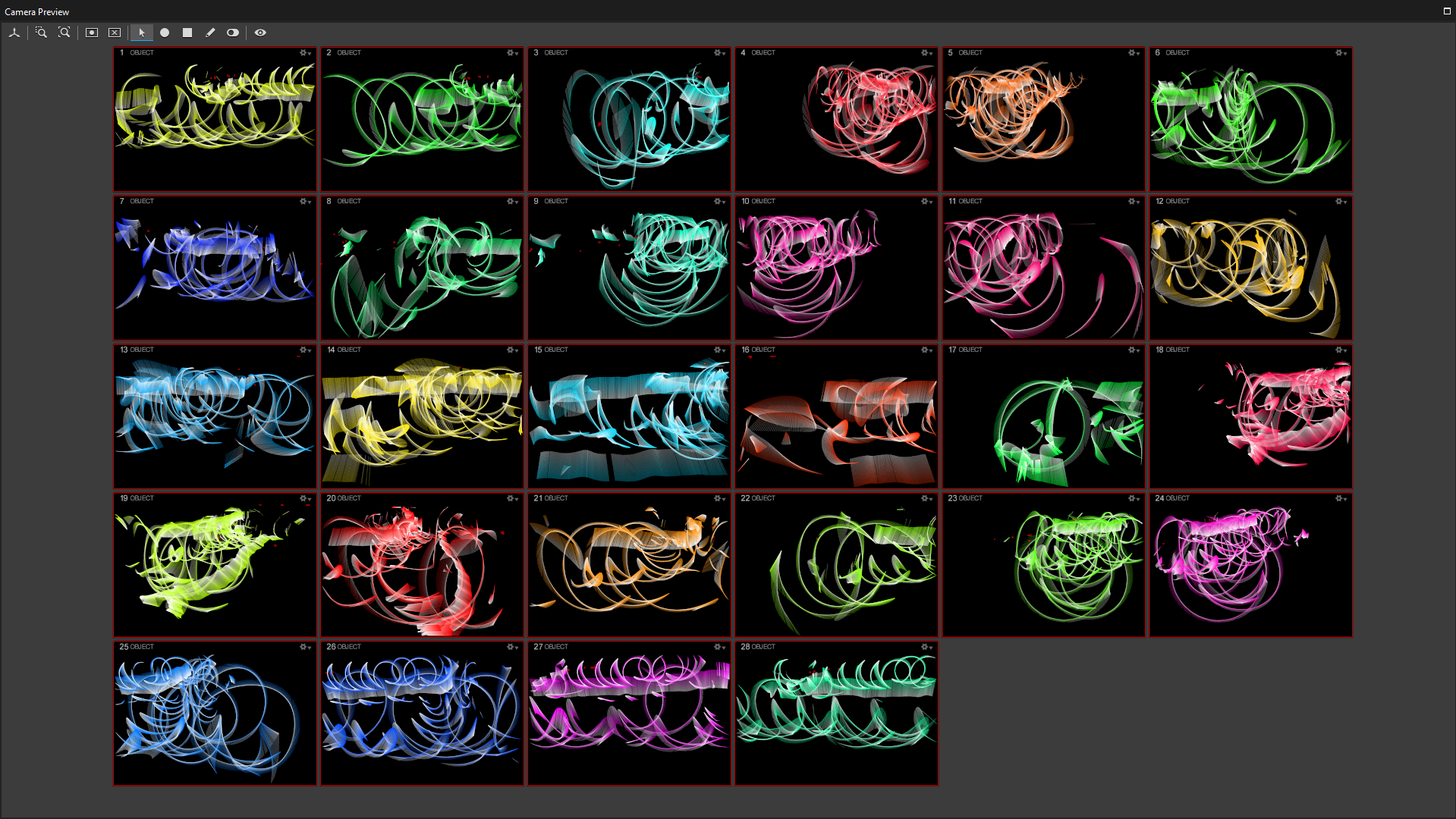
Reflections can be seen in the Camera Preview pane, which can be zoomed with the mouse wheel. Some small reflections on the floor can not be avoided and should not influence the tracking.
Switch back cameras to object mode by selecting all cameras in the Device pane and pressing the grayscale symbol to continue calibration.
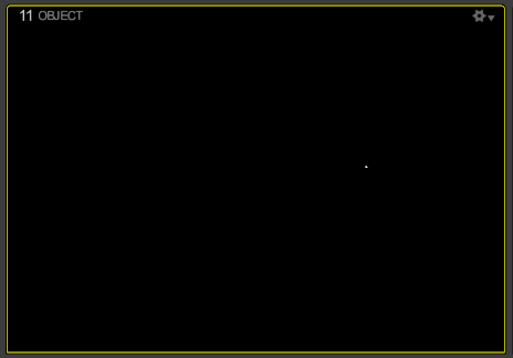
Ideally, the space should look like this (minor reflections):

Place a marker inside the tracking space as a reference.
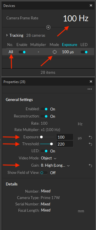
Select all cameras in the Devices Pane and adjust the following camera settings only if the reference is not clearly visible and/or there are a lot of false marker detections caused by reflections.
Calibration
Go to Menu > Layout > Calibrate to see all necessary calibration tools.

Two mode are available:
Make sure that the Tracking Mode is set to Passive. Otherwise, press Passive, Active Symbol in 3D View.

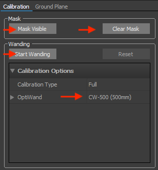
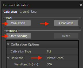
Once all the reflections are removed, Clear the previously set masks by pressing Clear Mask in the Calibration pane. Then set the masks again by pressing Mask visible. it is important that nobody is inside the space at this moment.
Select OptiWand CW-500 (500mm) in the Calibration pane as wand type and press Start Wanding.
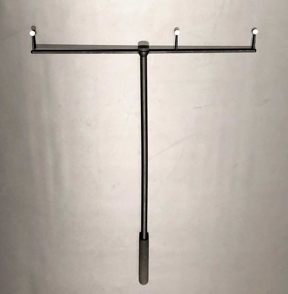
Take the passive wand (with grey reflectors), walk trough the tracking space and swing the wand continuously in front of all cameras and also in the middle of the space.
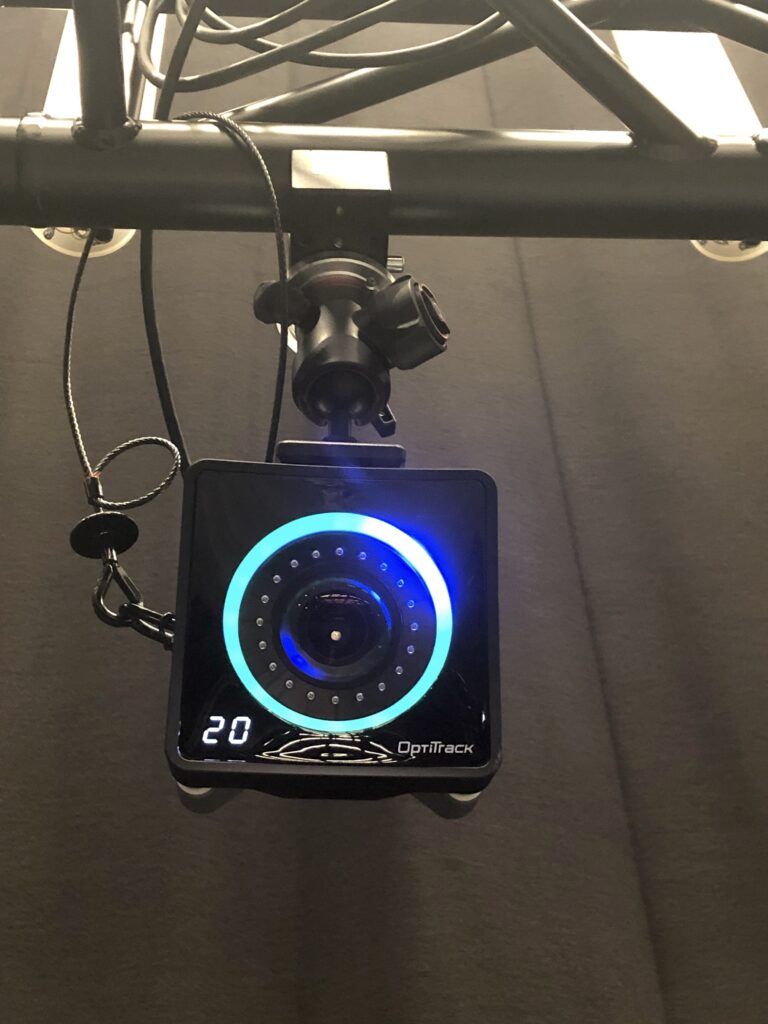
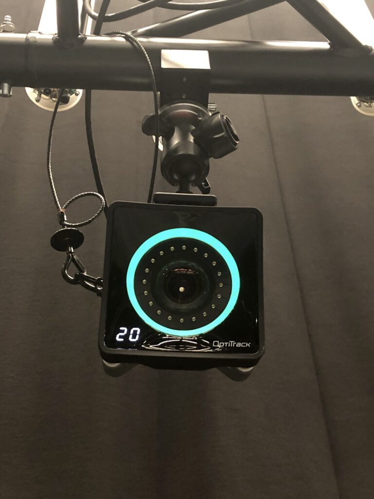
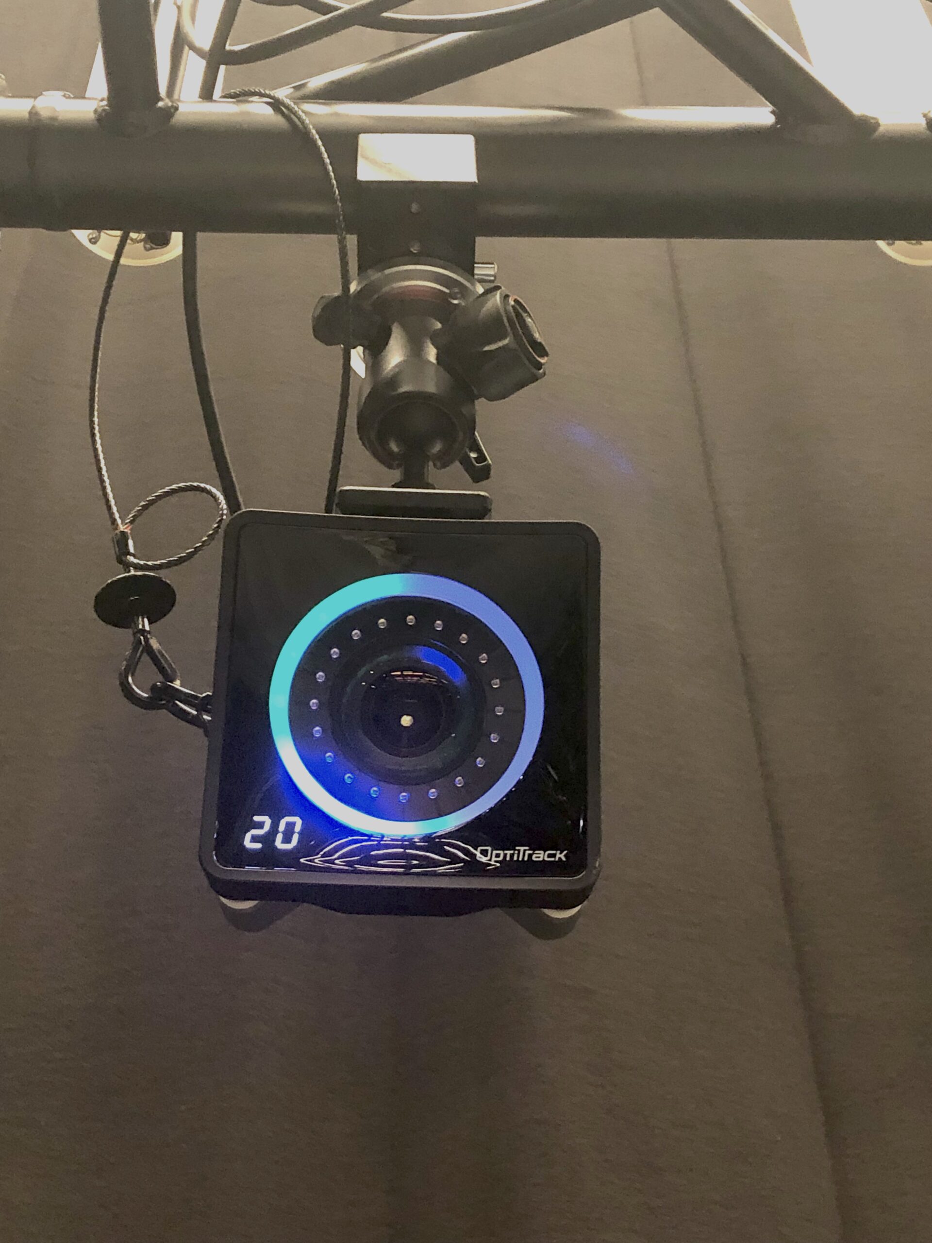
The cameras will indicate with a blue LED light, when they detecting the markers of the wand (also indicating the direction by the position of the blue light in the circle). The LED light will turn into green when the wanding was successful. Do not wand to close to the cameras, keep at least 3m distance from the cameras.
Keep on wanding util each cameras LED circle is fully green and you have reached at least 5000 samples on each camera.

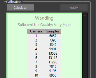
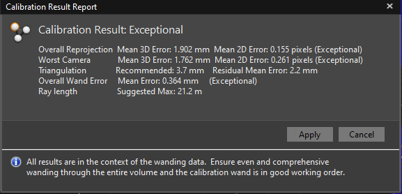
After wanding, press Calculate to solve the camera positions. Solving takes some time. Only if the result is Exceptional, you will get good tracking results. Otherwise, repeat the calibration process and check for reflections.
If you plan to use the tracking system with projections, take special care to position the groundplane as precise as possible over the markers.
Place the L shaped ground plane in the middle of the room, facing the long side to the large door.
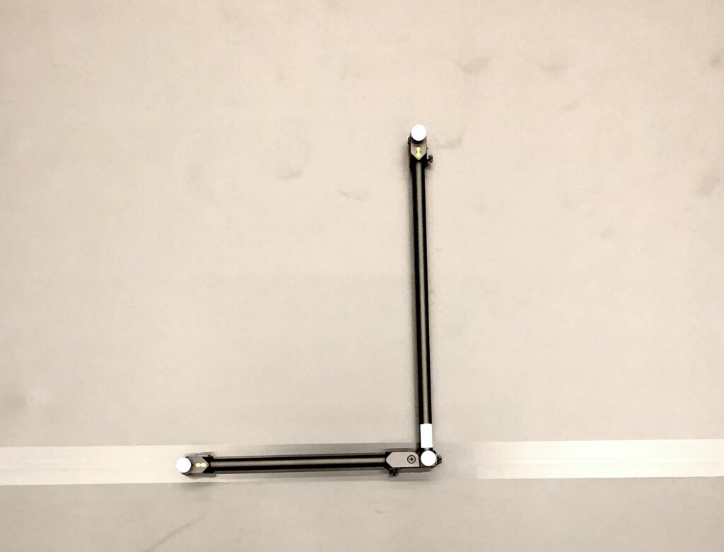

Press Set Ground Plane in the Ground Plane tab in the Camera Calibration pane.
If you get an error message, that no Ground Plane can be found, try to find the 3 Markers in the 3D view, select them and press Set Ground Plane again
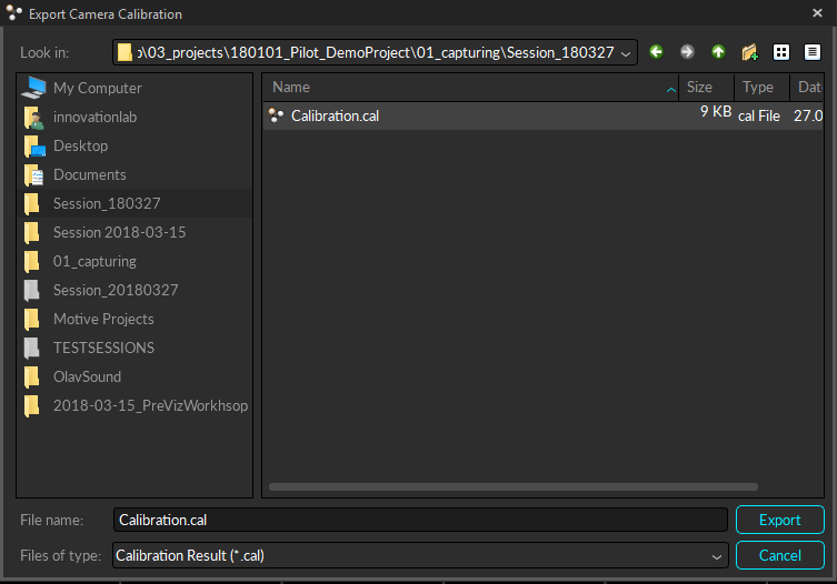
If setting Ground Plane is successful, you will be prompted to save the calibration. Choose your session folder and create a subfolder Calibration.
The calibration is now finished.
Make sure that the Tracking Mode is set to Active. Otherwise, press Passive, Active Symbol in 3D View.

Clear the previously set masks by pressing Clear Mask in the Calibration pane. Disable all infrared LED light of the cameras by pressing LED in the Device pane. Active wands do not need LED lights from the camera.
Select Micron Series (500mm) in the Calibration pane as wand type and press Start Wanding.
Take the active wand (with battery) and turn it on on the back, walk trough the tracking space and swing the wand continuously in front of all cameras and also in the middle of the space. The 3 active marker LED are on the opposite side of the On/Off switch, so make sure that they point to the camera.
The cameras will indicate with a blue LED light, when they detecting the markers of the wand (also indicating the direction by the position of the blue light in the circle). The LED light will turn into green when the wanding was successful. Do not wand to close to the cameras, keep at least 3m distance from the cameras.
Keep on wanding util each cameras LED circle is fully green and you have reached at least 5000 samples on each camera.


After wanding, turn off the wand and press Calculate to solve the camera positions. Solving takes some time. Only if the result is Exceptional, you will get good tracking results. Otherwise, repeat the calibration process and check for reflections.
Enable the LED lights of the cameras by pressing LED in the Device pane.
Make sure that the Tracking Mode is set to back to Passive. Otherwise, press Passive, Active Symbol in 3D View.
If you plan to use the tracking system with projections, take special care to position the groundplane as precise as possible over the markers.

Place the L shaped ground plane in the middle of the room, facing the long side to the large door.
Press Set Ground Plane in the Ground Plane tab in the Camera Calibration pane.
If you get an error message, that no Ground Plane can be found, try to find the 3 Markers in the 3D view, select them and press Set Ground Plane again
If setting Ground Plane is successful, you will be prompted to save the calibration. Choose your session folder and create a subfolder Calibration.
The calibration is now finished.
Setup Tracking Suit
Use the tracking suits ONLY with the black cotton-bodies underneath. It is the users responsibility to wash the bodies and bring them back in a timely manner.
- Choose a suitable suit size for the actor.
- Take off all the markers that are still on the suit.
- Make sure the suit fits tight and the top and pants cannot shift (use Velcro between jacket an pants)
- Put on shoes and gloves.
Inside Motive, go to Menu > Layout > Create.
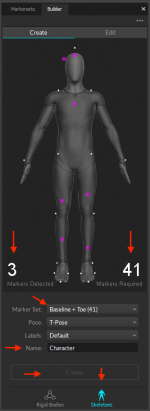
There are different marker sets (marker placements) for different use cases (with or without finger tracking). Choose in the Builder Pane > Skeleton under Markerset the makerset you wish to use. We recommend using the following different sets:
- Baseline + Toe (41 Markers) for body tracking
- Markerset Baseline + 11 Markers + Fingers (54 Markers) for body and finger tracking
Attach the markers according the 3D character.
Take care at the placement of the white markers at the joints. Set the markers in such a way, that the marker defines the axis of the joint and doesn’t move when the joint is used (ankle, knee, shoulder, elbow).
The purple markers are on bones and should be placed accordingly but can be vary a bit in exact position.
Make sure that all markers are still reflecting light and are not damaged.
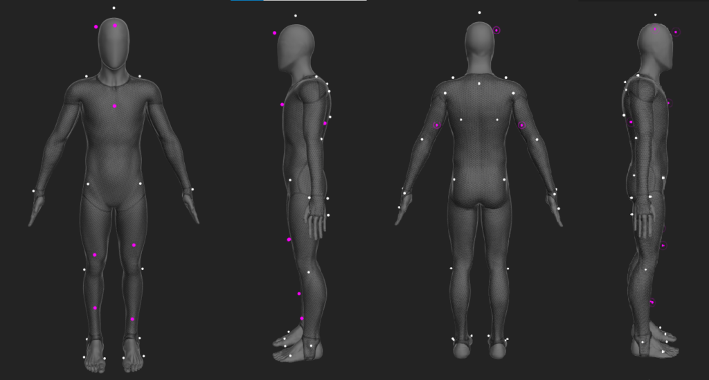
Make sure that the marker on the front upper leg are asymmetrical as indicated.
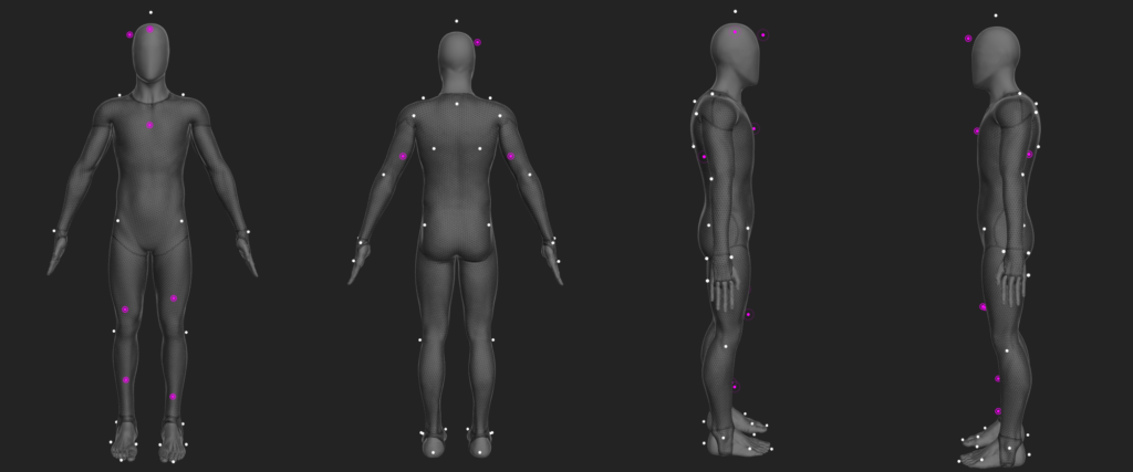
Make sure that the marker on the front upper leg are asymmetrical as indicated.

Make sure that the marker on the front upper leg are asymmetrical as indicated and the one on the lower back is on the left side.
Let the actor stand in the center of the space and take the T-pose.
The system should detect now all necessary markers. It shows how many markers are necessary and how many are detected. You can only create the character if you have the exact number of markers.
Give your character a Name and press Create.
If everything went right, the virtual character should appear inside perceptive view. Make sure the settings allow the display of the skeletons:

Adjust manually each body part if they appear to be off.

Setup Rigid Body
Setup a rigid body with markers or use one of the preconfigured ones. A rigid body should:
- Have at least 3 reflectors
- Reflectors should not be placed symetrical
- Reflectors should not be just in one line (i.e. like the wand)


Place the rigid body on the center of the trackingspace so that all markers can be seen by the cameras.
In Motive, go to Menu > Layout > Create.
Select all reflectors of the rigid body in the perspective view and Right Click on the Markers > Rigid Body > Create from selected markers.


Data Streaming
You can stream motion capture data live to different applications and other computers in the same network. A list of supported applications with plugins can be found on the Optitrack page.
In order to stream data, open the Streaming pane.

Enable the Streaming Engine by setting Broadcast Frame Data to on.
Now Check all the settings.
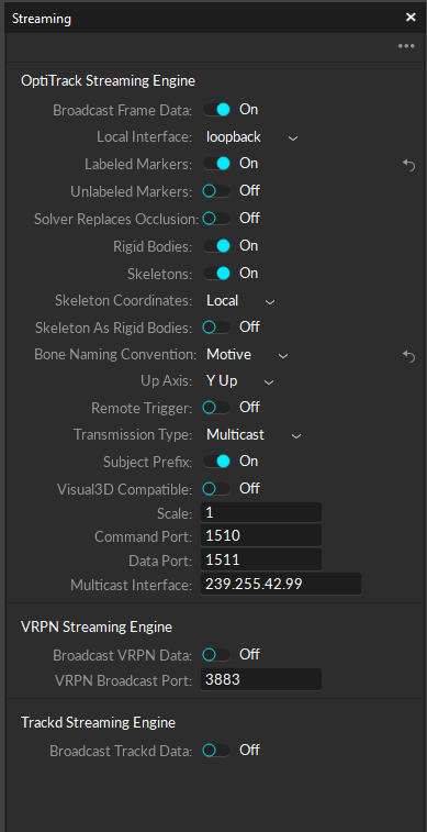
Choose on which network interface the data will be streamed.
If you only want to use the data on the same machine as Motive is running, set Local Interface to loopback. If you would like to send data to other computers, set Local Interface to 10.128.96.101.
- If you want to stream skeleton data (Characters),
enable Skeletons. - If you want to stream rigid body data,
enable Rigid Body.
Check also the other settings fits the settings of your receiver. Usually, this would be:
- Bone Naming Convention:
Motive - Up Axis:
Y Up - Transmission Type:
Multicast
For streaming to Unity, please refer to Unity and Optitrack Documentation.
If you want to get the streaming data as OSC – stream, you need to switch on the NatNet2OSC application.
Record animations
Motive > Menu > Layout > Capture

Make sure your session folder you created is active.
Give a new Take – name

and press record once ready.
Export animation
Select one or several takes you want to export. Right click > Export tracking data
Choose your session folder.
Choose FBX Binary Format with following settings:
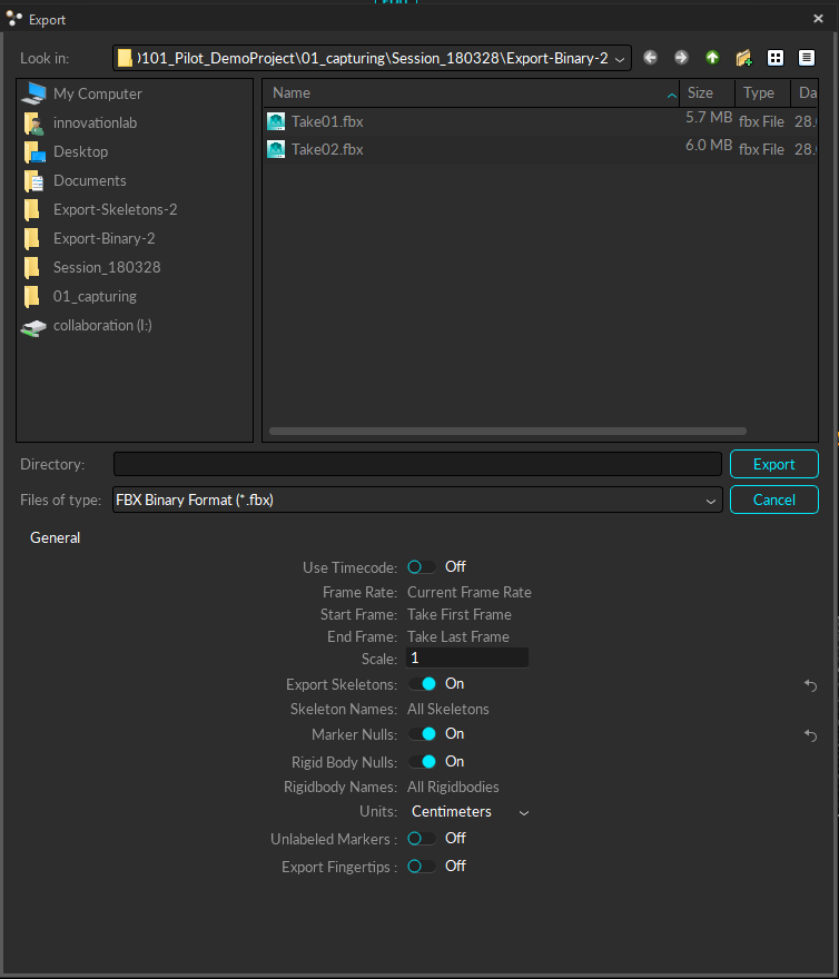
For every take, a FBX Binary file will be exported.